Overview
Spliced girder bridges are typically used for continuous structures in order to facilitate longer spans. In the past, spliced girders have been
limited to straight concrete I-girder sections. New spliced U-girder technologies now allow for curved U-shaped bridge options. Several have already been successfully constructed in Colorado.
Construction of these bridges
includes pre-casting either straight or curved u-shaped sections, supporting the pier and drop in sections, and splicing the sections together on temporary supports using post-tensioning. A lid slab is cast before the post-tensioning
is applied to increase the torsional resistance of the section. After the section is closed and stressed, conventional forms are placed between the boxes and a full depth deck is cast.
Span lengths for these structures can
be extended by providing haunched sections at the piers.
Advantages to this type of construction compared to conventional construction include:
- Lower fabrication times
- Faster construction
- Ability to span longer distances
- Increased aesthetics by providing a unified appearance
Characteristics of this type of construction include:
- Requires extensive Shoring
- Typically entails heavy girder sections and larger cranes to place.
- Requires more field and erection engineering than typical beam construction
- Stability must be designed for and maintained until superstructure is self supporting
- Requires monitoring of settlement and movement of temporary foundations during erection thru post-tensioning
General requirements and allowances for using spliced girders include:
Girders:
- Use standardized sections contained in the example drawings with standardized depths and standardized core form dimensions. Complete FDOT Standards similar to the FIB will not be available due to the unique design requirements
for a given site.
- Minimum of two girders per bridge
- Minimum 3 tendons per web
- Cast-in-place lid slab construction; Precast lid slabs are not allowed.
- Interior box lighting for post tensioned applications
- 72" minimum box girder height for PT sections
- For haunched girders, mildly reinforced field cast filled bottom flange build up is allowed.
- Future PT is not required.
- Mixing of curved and straight beams within a span is not allowed.
Allowance for inspection/access:
- Provide access into the box through the bottom slab for PT sections.
- Minimum 3'-0" diameter access holes in diaphragms
- Provide handles on either side of access holes for inspectors.
- 2'-0" minimum interior width measured along the top of the bottom slab
- Ramps up to diaphragm access holes are required.
Slab:
- Longitudinal mild reinforcing steel stress in the deck is limited to 24 ksi.
- Pretensioned concrete deck panels are not allowed as a forming system.
Pier Diaphragms: - Post-Tensioned integral piers are allowed.
Design Criteria
LRFD Bridge Design Specifications
FDOT Structures Manual
Post tensioning and box access requirements would be similar to FDOT precast segmental bridge requirements.
Specifications
FDOT Specifications where applicable
Technical Special Provisions required where standard specifications are not appropriate.
Implementation Plan
Implement as appropriate projects are identified.
Initial projects will require extensive coordination with the Structures Design Office to develop acceptable complete designs.
Contact Information
Will Potter, P.E.
State Structures Design Engineer
Phone: (850) 414-4267
e-mail: William.Potter@dot.state.fl.us | 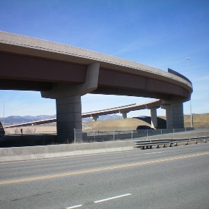
 Photos courtesy of: PCI